|
|
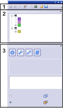
You can have the Fourier transform of an image computed for you. The Explorer group in the Fourier Transform tool window gives you an overview of which FT images are currently loaded in your software and to which images they belong. Should this tool window not be visible, use the View > Tool Windows > Fourier Transform command to show the tool window. Structure of the tool windowThe tool window is made up of several parts. Click on one of the areas in the tool window shown above to jump to the corresponding help topic. (2) The tool window's explorer (3) Fourier filters See also Options - Fourier Transform - General (1) The tool window's toolbarIn the Fourier Transform tool window's toolbar the following buttons are at your disposal. The buttons are described in the following table.
(2) The tool window's explorerIn the Fourier Transform tool window's Explorer group you can find all images that are currently loaded in the document group and that are linked to at least one FT image or an IFT image if applicable. The FT and IFT images are arranged below the source images. What you can do in the document areaClick on one of the entries in the Fourier Transform tool window to activate the FT image, the gray-value image, or the IFT image in the document group. When a lot of images and their corresponding FT images are loaded, this helps you to easily find the images that belong together.
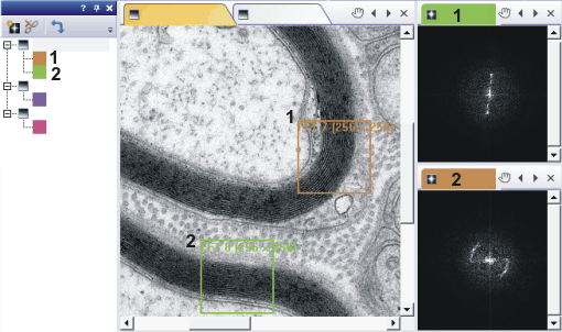
In the above example, three images that have FT images are loaded in the document group These images are listed in the tree view on the left of the Fourier Transform tool window. On the upper image, two image segments (1) and (2), from which FT images were calculated, are defined. Each FT image is assigned a color in the Fourier Transform tool window. The FT images' tab in the document group's header and the frame in the image segment have the same color. (3) Fourier filtersIn the Filter group in the Fourier Transform tool window, you can define different filters for the computation of Fourier images. Note: The settings in the Filter group are only available when you've selected an FT image in the document group or in the Explorer group in the Fourier transform tool window. You can use the filters to accentuate or filter out periodic structures. Define the size of the filter and its other properties and specify how you want the filters to be combined with each other. You can find more information on the individual filters and step-by-step instructions here. Creating a Fourier filterClick one of the big buttons in the Filter group to add a new Fourier filter to the active FT image. Several different Fourier filters are available. You will find different settings in the <Name of Fourier filter> settings group depending on which filter is active. When you add a Fourier filter to the FT image, an IFT image is automatically created and displayed in the document group. The filters effect the IFT image directly so that you can follow the changes in the IFT image in real time. You can find the settings for the different filters in the table.
Managing an image's Fourier filterIn the field below, all defined filters are listed. The filters are numbered consecutively, "Annular <consecutive number>" for example. Select or clear the check boxes to activate or deactivate filters. Click the name of the filter to display its filter settings. The corresponding filter settings, <Name of Fourier filter> settings, have the same consecutive number. Double click the Selecting the type of Fourier filterIn the Type field, you can select the type of filter. Select the Inside option if you want the filter range to be inside the circles. The filtered image now only contains the information from the frequency ranges that are outside of the defined filter ranges. Select the Outside option if you want the filter range to be outside the circles. The filtered image now only contains the information from the frequency ranges that are inside the defined filter ranges. If you want to enhance a periodic structure with a filter, for example, you can define a Fourier filter that contains the frequency range to which this periodic structure belongs and then select the Outside option.
The original image (1) shows a periodic structure that creates point shaped reflexes in the Fourier image (2). A grid shaped Fourier filter has been defined in the Fourier image (2). With the Outside option, the filtered image (3) shows the periodic structures significantly more clearly. This is because all of the frequencies that are outside of the lattice aren't represented in the image any more. Combining Fourier filtersIn the Combination group, select how all of the defined filters are combined with each other. You can select either the Intersection or the Union option.
6022 24022015 | ||||||||||||||||||||||||||||||||||||||||||||||






 button next to a filter name to delete that filter.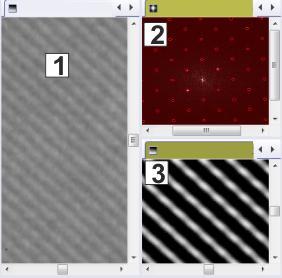
 Select the
  Select the