In the Fourier transform tool window, you'll find the Filter group. You can define filters for Fourier images here. You can use these filters to define frequency ranges in the Fourier image or to exclude ranges.
Example: You can use a filter to filter object structures out of a gray-value image with periodic patterns. To do this, first compute an FT image from the source image. Apply a suitable filter and create a filtered FT image. An inverse Fourier transform transforms the FT image back into a gray-value image. The resulting image is a filtered gray-value image.
You can save the filters you defined and use them later on different Fourier images. If you define more than one filter, they will all be combined with each other. You set the way they are combined in the Combination group.
Note: The settings in the Filter group are only available when you've selected an FT image in the document group or in the Explorer group in the Fourier transform tool window.
See also
Tool Window - Fourier Transform
Defining a Bandpass filter

The Bandpass filter defines a lower and an upper threshold in the frequency domain. The resulting filter range contains all frequencies (in the X and Y dimensions) that are larger than the lower threshold and smaller than the upper threshold.
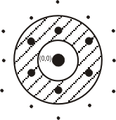
With an bandpass filter, the frequency range is limited by two circles. The center of both the circles is the origin of the Fourier image.
1.Select the FT image in the Fourier transform tool window or in the document group.
2.Click the Bandpass button.
•In the FT image, two concentric circles are displayed that show the thresholds of the annular filter. The center of the circles is the center of the Fourier image.
•An IFT image is created in a new image window.
•The filters that have been defined are listed below the Type field in the Fourier transform tool window. The filters are numbered consecutively, "Bandpass <consecutive number>" for example.
3.Click on the circles in the FT image.
•Two handles are displayed which you can use to change the size of the circles.
•Alternatively, you can define the filter thresholds in the Lower and Upper fields. The red area is the filter area. The black area is not detected by the filter.
4.Click on each of the handles in turn and drag the circles to the size you want.
5.The filter has a direct effect on the IFT image.
5.Select the filter type in the Fourier transform tool window's filter settings. If the filter settings are not displayed, select the FT image in the Explorer group and then select the corresponding filter in the field under the Type field. The type of filter defines whether the filter range is located inside or outside the lines. You can select between the Inside and Outside types.
6.Create new filters if necessary. All of the filters that have been defined are listed below the Type field. Select the filters you want and, in the Combination group, specify whether the filters are combined using the Intersection or the Union option.
Saving filters
7.Click the Save Filters button to save the filter configuration.
Defining a Sector filter

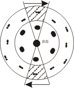
The Sector filter defines a sector in the frequency domain that consists of two symmetrical areas. You can use the Sector filter to filter structures that have a particular alignment, for example.
1.Select the FT image in the Fourier transform tool window or in the document group.
2.Click the Sector button.
•Two lines are displayed in the FT image. They intersect in the center of the image to form two point symmetrical sectors.
•An IFT image is created in a new image window.
•The filter that has been defined is listed below the Type field in the Fourier transform tool window. The filters are numbered consecutively, "Sector <consecutive number>" for example.
3.Click on the lines in the FT image.
•Two handles are displayed which you can use to move the lines.
•You can use the handle on the center line to rotate the sectors around the center point.
•You can use the handle on the outer line to increase or decrease the angle of the two sectors.
•Alternatively, you can define the filter thresholds in the Orientation and Opening fields. The red area is the filter area. The black area is not detected by the filter.
4.Click on each of the handles in turn and drag the line to the position you want.
•The filter has a direct effect on the IFT image.
5.Select the filter type in the Fourier transform tool window's filter settings. If the filter settings are not displayed, select the FT image in the Explorer group and then select the corresponding filter in the field under the Type field. The type of filter defines whether the filter range is located inside or outside the lines. You can select between the Inside and Outside types.
6.Create new filters if necessary. All of the filters that have been defined are listed below the Type field. Select the filters you want and, in the Combination group, specify whether the filters are combined using the Intersection or the Union option.
Saving filters
7.Click the Save Filters button to save the filter configuration.
Defining a Blob filter

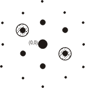
The Blob filter is composed of two circles. These circles are symmetrical to each other because of the Fourier image's symmetrical properties.
1.Select the FT image in the Fourier transform tool window or in the document group.
2.Click the Blob button.
•Two circles appear on the FT image. They are point symmetrical to each other with respect to the origin of the Fourier image. Two handles are displayed on each circle with which you can change the circle's size and position.
•An IFT image is created in a new image window.
•The filter that has been defined is listed below the Type field in the Fourier transform tool window. The filters are numbered consecutively, "Blob <consecutive number>" for example.
3.Click on one of the handles and drag the circle to the position you want or change its size.
4.With the handle in the center of the circle you can move the circles around the FT image and change the distance between the circles.
•You can use the handle on the edge of the circle to change the size of the circle.
•Alternatively, you can change the size and position of the circle in the Orientation, Distance and Radius fields.
•The filter has a direct effect on the IFT image.
4.Select the filter type in the Fourier transform tool window's filter settings. If the filter settings are not displayed, select the FT image in the Explorer group and then select the corresponding filter in the field under the Type field. The type of filter defines whether the filter range is located inside or outside the circles. You can select between the Inside and Outside types.
5.Create new filters if necessary. The filters that have been defined are listed below the Type field. Select the filters you want and, in the Combination group, specify whether the filters are combined using the Intersection or the Union option.
Saving filters
6.Click the Save Filters button to save the filter configuration.

The Lattice filter is made up of numerous circular or elliptical frequency areas. These frequency areas are arranged in a grid. The lattice is defined by two basis vectors.
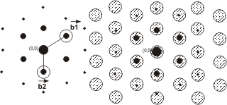
The two basis vectors, b1 and b2, define the lattice.
1.Select the FT image in the Fourier transform tool window or in the document group.
2.Click the Lattice button.
•In the FT image, numerous circles are arranged in a grid. Three handles are shown in the two basis vectors. You can use them to define the grid.
•An IFT image is created in a new image window.
•The filter that has been defined is listed below the Type field in the Fourier transform tool window. The filters are numbered consecutively, "Lattice <consecutive number>" for example.
3.Click on one of the handles and drag the circle to the position you want or change its size.
•You can use the handle on the edge of the circle to change the size of the circle.
•With the handles in the center of the two circles you can change the position of the circles and thereby the distance between them.
•Alternatively, you can change the size of the circles and the lattice in the Orientation, Distance and Radius fields.
•The filter has a direct effect on the IFT image.
4.Select the filter type in the Fourier transform tool window's filter settings. If the filter settings are not displayed, select the FT image in the Explorer group and then select the corresponding filter in the field under the Type field. The type of filter defines whether the filter range is located inside or outside the circles. You can select between the Inside and Outside types.
5.Create new filters if necessary. The filters that have been defined are listed below the Type field. Select the filters you want and, in the Combination group, specify whether the filters are combined using the Intersection or the Union option.
Saving filters
6.Click the Save Filters button to save the filter configuration.
00282 10092014