|
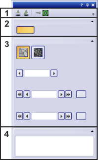
Use the Microscope Control tool window to view and edit information about your current microscope settings. Should this tool window not be visible, use the View > Tool Windows > Layers command to bring up the tool window.
Prerequisite: All supported microscopes are offered during the installation of your software. After the first time you start your software, select the type of microscope in the Acquire > Device > Device List dialog box. You can find the microscope type in the Microscope list.
Remote-controlled microscope
If your transmission electron microscope can be controlled remotely by your software, then you can access some microscope units directly from your software. To do this, use the Microscope Control tool window. For example, you can change the magnification.
Microscope without remote control
If your transmission electron microscope cannot be controlled remotely by your software, use the Microscope Control tool window to enter the current microscope settings manually, for example the magnification. This data will be saved along with the acquired images. You can find more information on working with a transmission electron microscope without remote control here.
Structure of the tool window
The tool window is made up of several parts. Click on one of the areas in the tool window shown below, to jump to the corresponding help topic.
Note: The tool window's appearance depends on the hardware components that are currently present and can, as well, be changed by the user. For this reason, it can happen that in your software version not all of the groups that are listed are available.
Further information about microscope control functions for specific types of microscope can be found here.
(1) Toolbar of the tool window
(2) Selecting the observation method
(3) Controlling the microscope units
(4) Viewing the microscope settings
See also
Hardware - Microscope
(1) Toolbar of the tool window
In the Microscope Control tool window, a number of buttons are available in the toolbar.
   
The following table lists the buttons which are available by default on the toolbar.
|
Beam Blanker
|
Click the Beam Blanker button to switch the Beam Blanker on or off.
|
|
Fluorescent Screen
|
Click the Fluorescent Screen button to raise and lower the fluorescent screen.
|
|
Eucentric Height
|
Click the Eucentric Height button to set the eucentric height.
|
|
Astigmatism
|
Click the Astigmatism button to correct an astigmatism in the image.
|
Beam Blanker
Click the Beam Blanker button to switch the Beam Blanker on or off.
Note: The beam blanker's current status is displayed in the Microscope Info group.
When the beam blanker is switched off, it has the Opened status. The electron beam will not be deflected anymore. The sample is fully illuminated and you can observe it.
When the beam blanker is switched off, it has the Closed status. The electron beam will be deflected and/or a shutter is closed. The sample as well as the camera will now not be illuminated anymore.
Fluorescent Screen
Click the Fluorescent Screen button to raise or lower your transmission electron microscope's fluorescent screen.
Note: The fluorescent screen's current status is displayed in the Microscope Info group.
When the fluorescent screen is switched off, it has the Down status. Now, you can see the image on your microscope's fluorescent screen and look through the microscope's eyepiece when you focus the sample.
Eucentric Height
Note: The eucentric height can only be automatically set if your microscope is equipped with a motorized Z-drive.
Click the Eucentric Height button to set the eucentric height in the current image. By setting the eucentric height, you ensure that the image doesn't move when the sample holder is rotated.
Astigmatism
Prerequisite: To be able to correct the astigmatism using this button, you first have to have performed the Stigmator calibration calibration process successfully. You can find more information on this topic here.
Click the Astigmatism button to correct an astigmatism in the image. An astigmatism is caused by defective lenses and leads to a distorted image. The software corrects an astigmatism with the help of stigmators.
back to the structure of the tool window
(2) Selecting the observation method
What is an observation method?
An observation method comprises all microscope units that can be controlled by your software and the definition of their state. This means that the microscope can be set up for a particular task with one click.
Two observation methods have been predefined.
Automatic observation method at image acquisition
When you switch to the live-image or acquire an image, your system automatically switches to the Camera Mode observation method.
When you are working with a camera that is mounted below the microscope column, the fluorescent screen on your transmission electron microscope is raised and the beam blanker is turned off.
When you're working with a side-mounted camera, the camera will be retracted from the microscope column and the beam blanker is turned off.
The Camera Mode observation method ensures that the camera is illuminated and that you see an image in your software regardless of your current microscope settings.
If the Manual observation method was active, this observation method will automatically be deactivated. In the Microscope Control tool window, the Manual button will not appear clicked anymore.
Manual observation method, when you are working without a camera
If you don't need your camera, because you prefer to focus using the microscope's eyepiece for example, you can use the Manual observation method.
To do this, click the Manual button. The Manual button appears clicked. You can recognize this status by the button's colored background.
When you are working with a camera that is mounted below the microscope column, the fluorescent screen on your transmission electron microscope is lowered and the beam blanker is turned off.
When you're working with a side-mounted camera, the camera will be retracted from the microscope column and the beam blanker is turned off.
When you change the microscope settings, by activating the beam blanker for example, the Manual observation method is automatically turned off.
back to the structure of the tool window
(3) Controlling the microscope units
If your transmission electron microscope can be controlled remotely by your software, then you can access some microscope units directly from your software.
Selecting the imaging or diffraction mode
Select the microscope's imaging mode by clicking the Imaging or Diffraction button.
In Imaging mode, the Magnification field can be used for entering the microscope magnification.
In Diffraction mode, the transmission electron microscope is controlled in a way that enables the display of the diffraction image. In this mode, the Camera Length field can be used for entering the camera length.
Note: The high intensity of the electron beam can harm the camera.
After image acquisition, switch to Imaging mode immediately or use the beam blanker to avoid any damage to the camera.
When working in Diffraction mode, a calibration of the camera length is required. You can find more information on the Camera Length calibration process here.
Changing the magnification
Select the Imaging mode. Enter the magnification you want in the Magnification field or use the arrow buttons to set it. Alternatively, you can also change the magnification in the live-image itself by rotating the mouse wheel while pressing the [Ctrl] key.
You can set the magnification directly on your transmission electron microscope. Then the magnification you've set will automatically be transferred to your software and displayed in the Magnification field.
Changing the camera length
Select the Imaging mode. Enter the camera length you want in the Camera Length field or use the arrow buttons to set it. Alternatively, you can also change the camera length in the live-image itself by rotating the mouse wheel while pressing the [Ctrl] key.
Note: The Camera Length field is only visible if the Diffraction mode is selected. Use the Camera Length calibration process to acquire correctly acquired images. You can find more information on this topic here.
Tilting the sample holder
When you are using a tilt holder that can be controlled from your software, you can find functions for the tilting of the sample holder in the Microscope Control > Microscope Units group. Enter the tilt angle you want in the field or use the arrow buttons to set it.
Alternatively, you can change the sample holder's tilt angle by rotating the mouse wheel while pressing the [Shift] key.
Click this button [ 0° ] to tilt the sample holder back to a horizontal position.
back to the structure of the tool window
(4) Viewing the microscope settings
In the Microscope Info field, you can find the current microscope configuration. Here you can find all microscope units whose status can be read remotely. One example is which high voltage is used.
All information in the Microscope Info field is recorded as additional information along with the image itself during image acquisition. You can view the microscope information in the Properties tool window.
Note: Most of the data will only be saved along with your image when you use the TIF or VSI file format.
back to the structure of the tool window
00290 04032015
|