The Options dialog box offers several preferences that apply to interactive measurement functions. In the Tools > Options > Measurement > Measurement Display dialog box, you specify how the measurement objects in the image are to be labeled.
Description of the function groups
See also
Overview - Measurement Options
Text
The settings in the Text group apply for measurements on an image and on a chart document. In this group, select the labeling that you want to use for your measurement objects.
Clear all of the check boxes in the Text group, to not have the measurement objects in the image or chart labeled at all.
Numbering measurements serially
Select the Show ID check box to number consecutively all of the objects that were measured . Use this function, e.g. to help you keep a clear overview of how many measurements you have carried out. Thereby, you can also reproduce the measurements sequence at any time.
Each measurement object keeps its measurement ID once it has been assigned. For example, if there are three measured objects on the image and you delete the measurement object with ID 2, the image will still contain the two measurement objects 1 and 3.
The next measurement object will be given the ID 4, as all objects are number in order.
You can also adopt the measurement ID in the results sheet. To do, select the Show ID column check box, located in the Options > Measurement > Results dialog box.
Naming measurements
In the Measurement tool window, you can freely assign a name for every measurement, in the Name column. Double click with your left mouse button in the Name column. A flashing cursor will appear. Enter a name for your measurement.
Select the Show name check box, located in the Tools > Options > Measurement > Measurement Display dialog box to have the name of the measurement object displayed in the image or chart.
Displaying measurement results
Select the Show value check box to have the measurement objects labeled with the measurement value and the unit of magnitude. With an area measurement, the labeling will then be, for example, 50 µm².
When you measure certain measurement objects, such as circles, numerous values will be measured simultaneously. In this case, the value displayed in the first position in the Select Measurements dialog box, will be displayed in the image.
Including the measurement name
Select the Include measurement name check box to add the name of the measurement parameter to the measurement value. With an area measurement, the label would then be Area 50 µm², for example.
If you aren't working with an English version of the software: You can also output all of the measurement results in English at any time. To do this, select the Show overlay and exported results in English check box, located in the Options > Measurement > General dialog box.
Positioning the measurement label
The measurement labels are written below the measurement object in the image; they are written below the position where the definition of the measurement objects begins. Thus, you determine the position of the labeling, e.g., when defining a measured distance, by clicking on the starting point.
The measurement labels have their own handles. You can move a measurement label at any time. To do so, click on the handle and move it with the left mouse button depressed, to the required position.
Note: You can only change the measurement label for individual measurements. By doing this you won't change the measurement label's default position for future measurements.
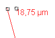
The illustration shows a line measurement. To the right of the measurement result you can see the handle for the measurement label.
New measurement objects
In the New measurement objects group, selected settings only concern measurement objects which you define from now onwards. The appearance of existing interactive measurements will not be changed by this.
You can also display existing measurement objects in a different way. To do so, select the measurement object, and click your right mouse button, to open a context menu. The context menu contains various commands with which you can alter the appearance of the measurement object.
Changing the color of labels
The Text color options apply for measurements on an image and in a chart document.
Select the Alternating colors option, to automatically match various colors to various measurement objects within a measurement. The color affects the display of the interactive measurement object and the corresponding label in the image. The order of the colors is preset.
Select the Fixed colors option to label the measurement objects with a color.
Click on the color field next to the Fixed colors option, to open a color table. You can select one of 16 possible colors in the color table.
Altering the display of the measurement objects on an image
The following settings only apply for measurements on an image. Measurement objects on a chart document do not take account of these settings.
By default, a transparent setting is set for the labeling of a measurement so that you cover as little as possible of the image. Should you wish to have a colored background for the labeling of the measurement objects, select the color you want from the Background color color table.
Enter a value for the font size in the Font Size field.
Enter a value for the line width in the Line thickness field.
Adding helper lines to line measurements
Select the Add helper lines to line measurements check box to have helper lines displayed for the Arbitrary Line  , Vertical Line
  , and Horizontal Line
  measurement functions. The helper lines run vertically on the measured distance and help you to align the measured distance exactly with the image structure.
Select the Show long helper lines check box. Now the helper lines belong to the measurement object and remain visible even after you have finished the measurement.
Clear the check box if you only want the helper lines to be visible during the definition of the measurement object.
4403 13032014